Knowing the whole from multiple perspectives
We usually research products, services, or organizations from multiple perspectives to understand their state.
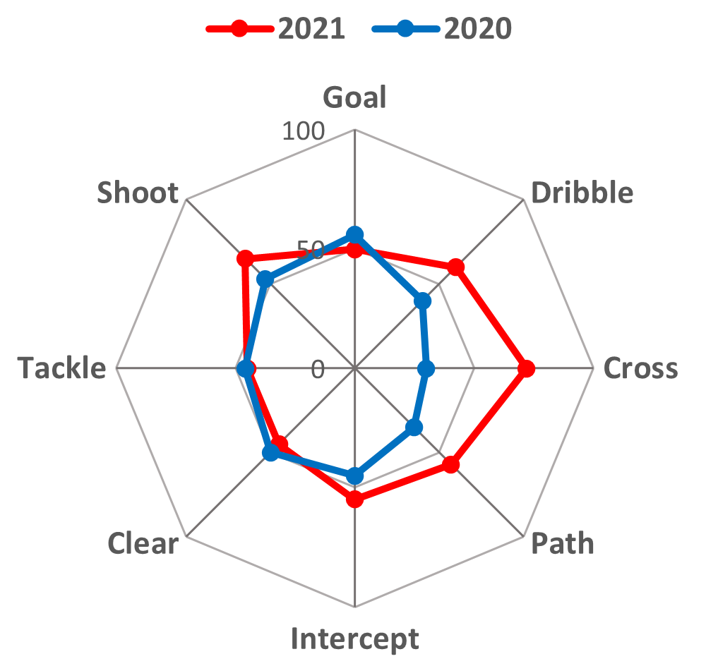
For example, the status of an organization, such as the strength of a sports team or corporate social responsibility, can be examined from multiple perspectives. People often use radar charts to show multiple scores to capture the whole. Figure 1 shows an example of soccer team stats on radar charts.
The radar chart for 2021 superimposed on that for 2020 is shown in this example. Such results as this sample come down to a sequence of the radar chart over several years.
If we can quantify each radar chart in this research, we can obtain a change in the status over time with numeric change and analyze the correlations between status and conditions. Then we can make predictions.
Radar chart quantification is nothing more than obtaining a single integrated value from multiple perspectives scores. There are many possible methods for its calculation. However, since the radar chart shows the scores from multiple perspectives, the quantification to correspond with the visual judgment is desirable. For example, it is either that the scores are well-balanced high, that the score is balanced but low overall, or that the score is uneven and unbalanced.
RADAR CHART POWER (RC-POWER) ® is a quantified index of a radar chart, which corresponds with the visual judgment of the radar chart. The RC-POWER calculated from the shape and size of the radar chart means whether the scores are high in a well-balanced manner. So, it corresponds to visual judgment.
Here is an example of replacing the experimental result of the sequence of radar charts with the RC-POWER, quantifying the change, and obtaining the estimated value under specific conditions.
It is an example of an analysis of the effect of agent doses on a subject in a trial study for cancer treatment. The results were given as the sequence of radar charts by the doses. This analysis promoted the creation of the RC-POWER.
Next, we calculated the integrated value by methods other than RC-POWER using identical scores. We will consider these issues by focusing on how each event from multiple perspectives shown in the radar chart is perceived.
Evaluate tube formation test with RC-POWER
Contents
- What is the tube formation test?
- Materials and Methods
- Quantification of the sample images
- Inhibition process shown on radar charts
- Inhibition process by integration using RC-POWER
- Inhibition process by integration using methods other than RC-POWER
- Integration according to how each event from multiple perspectives is perceived
- Summary
If you want to catch the gist of the contents in a big way, please go to the middle of “What is the tube formation test?”
Then skip to “Inhibition processes shown on radar charts“. Please read the rest of “Materials and Methods” to confirm the content.
What is the tube formation test?
The tube formation test is a study in the development of cancer treatments.
As shown in Figure 2, cancer grows by building a network of blood vessels that supply nutrients and oxygen. Therefore, starvation caused by inhibition of the construction of blood vessels can be a treatment strategy that provides cancer to shrink and metastasis to suppress. One such treatment is the inhibition of angiogenesis, whose process always performs a tube formation test.

Figure 2 Cancer that grows by angiogenesis.
As a method of analyzing sample images obtained in the test, we will introduce an example of analysis where the integration of five perspective scores extracted from the images provides the quantitative inhibition process.
If you would like to move to “Inhibition process shown on radar charts“, click here.
Cancer does not have blood vessels by nature. However, when cancer cells increase to a certain extent, they release factors to induce new ones from the surrounding blood vessels. These factors cause new blood vessels and vascular networks.
This physiological phenomenon is called angiogenesis.
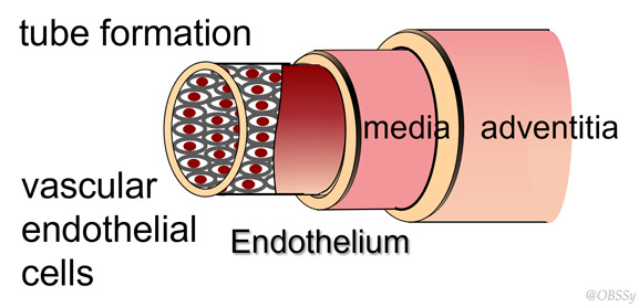
Here, Figure 3 shows the structure of blood vessels. The lumen of a blood vessel is covered with endothelium-lined vascular endothelial cells. The lumen formed by endothelial cells is lined with the media and the adventitia to form blood vessels.
Materials and Methods
In the development of angiogenesis inhibitors, we first search for candidates for the inhibitors.
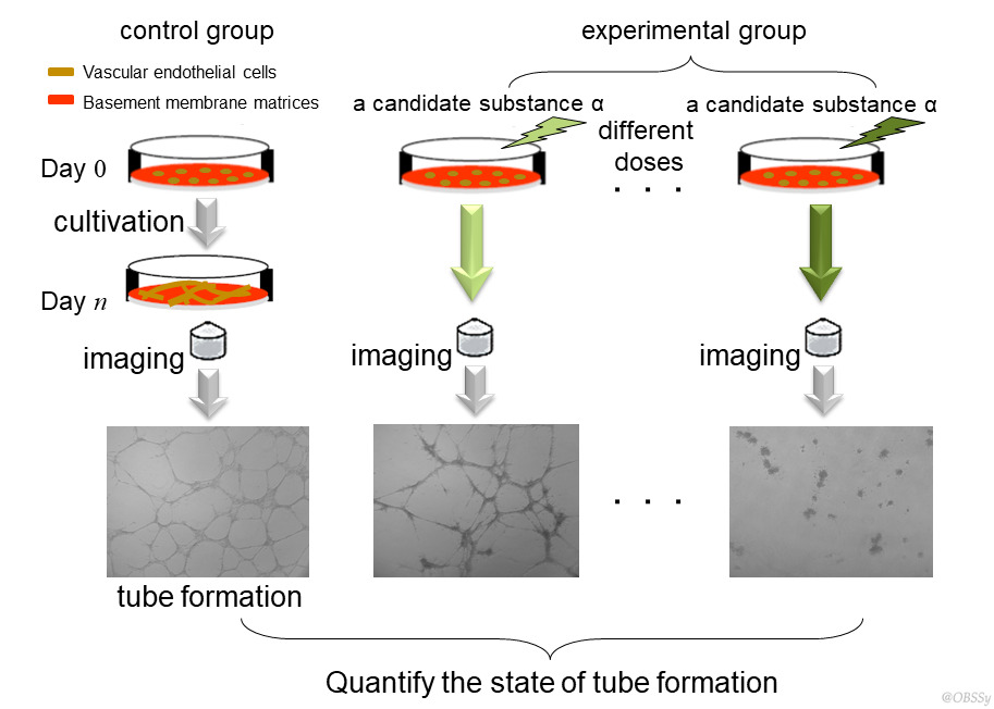
As for the identified candidates, the tube formation test confirms an inhibitory effect and investigates how inhibition depends on the doses. The test performs under the process of vascular endothelial cells reproducing tube formation in Petri dishes (Figure 4).
The tests are always going side by side for the control and the experiments using different doses of the candidates. Cells are cultured under identical conditions for a defined period and then captured into images under a microscope.
The control image shows mesh patterns due to the tube formation, but the experimental images show partially or none of them in a dose-dependent manner
The state of tube formation is quantified as mesh patterns from these images and then analyzed for the correlation to doses. The score of the state is relative to the control.
Quantification of the sample images
To confirm the efficacy of the analysis method, we performed a tube formation test with the anti-angiogenic agent Suramin, a clinically used angiogenesis inhibitor.
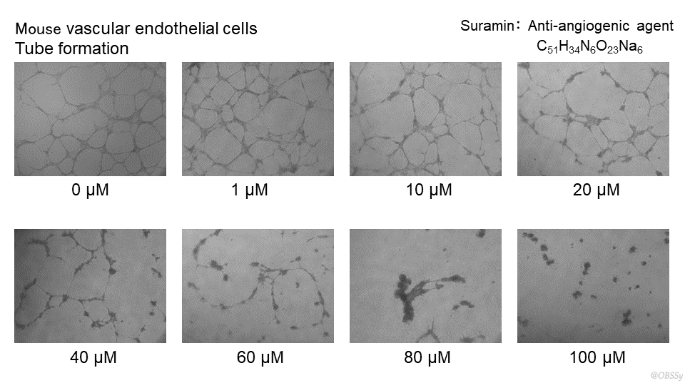
Figure 5 shows an example of images from the tube formation test. In the experiments, the agent doses were varied to 1μM, 10μM, 20μM, 40μM, 60μM, 80μM, and 100μM.
Figure 5 Tube formation test with Suramin.
The mesh pattern due to tube formation is collapsed gradually as the dose increases. The images were analyzed with five perspectives and quantified to take five scores to the state of tube formation for each dose. Their scores are percentages based on the mean of each of the control. Please refer to these papers for detailed image analysis.
- 立野玲子, 小倉 潔, 後藤敏行:画像解析による管腔形成試験の評価方法および評価装置, 特許5783485, 2015.7.31 (Japanese patent)
- Minamikawa-Tachino R, Ogura K, Gotoh T.: Mesh-loosening quantification of inhibition of angiogenic tube formation through image analysis. Assay Drug Dev Technol. 2013 Feb;11(1):25-34.
Inhibition process shown on radar charts
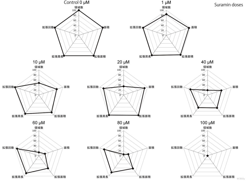
Figure 6 shows a radar chart sequence of the results of analyzing the samples in the control and the experimental group from five different perspectives. It shows the relative relationship between the condition in the control group and the experimental one at each dose.
Click to enlarge
Figure 6 The radar charts of the experimental group compared with the control one on the status of tube formation.
The state of tube formation is a regular pentagon with 100 for all five scores in the control group. However, the experiments represent morphological changes of pentagons corresponding to the doses.
The regular pentagon collapses after the administration of Suramin. The shape of the pentagons is almost the same, but their size gradually decreases up to 40μM. The morphology changes distinctly at 60μM. The overall size decreases to 80μM. The pentagon finally disappears and becomes a single point at 100μM.
Inhibition process by integration using RC-POWER
Let it be that the state of tube formation represents the activity forming the tube. That is, it is tube-forming activity, which is shown on the radar chart and quantified by the RC-POWER.
The control provides the tube-forming activity with a radar chart of the regular pentagon having all scores of 100, whose RC-POWER is 100. The experiments provide the tube-forming activity with radar charts of the distorted pentagon having scores less than 100 corresponding to the doses. Each RC-POWER is less than 100.
The inhibition process suggests the process that causes RC-POWER to decrease.
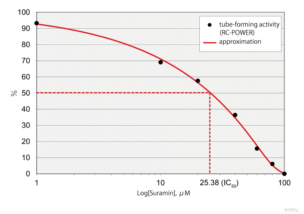
Figure 7 presents the inhibition process with a gradual decrease with increasing dose and then reaching zero at 100µM. The tube-forming activity was approximated as a curve by a general logistic function to obtain a dose-response inhibition curve, and the half minimal inhibitory concentration (IC50), an index of pharmacological action, was also calculated.
Click to enlarge
Figure 7 Dose-dependent inhibition curve by Suramin.
This IC50 is consistent with already published biochemical reports and similar analyzer estimates. The RC-POWER provides valid results for the tube formation test by Suramin, a clinically used anti-angiogenic agent.
Please see page 3 of the following document for IC50 on the analyzer compared.
APPLICATION NOTE BD Biosciences – Bioimaging Systems: 血管新生モデルとしての血管内皮細胞チューブ形成の画像解析 https://www.bdj.co.jp/pdf/65-060-00.pdf (accessed September 7, 2022)
Inhibition process by integration using methods other than RC-POWER
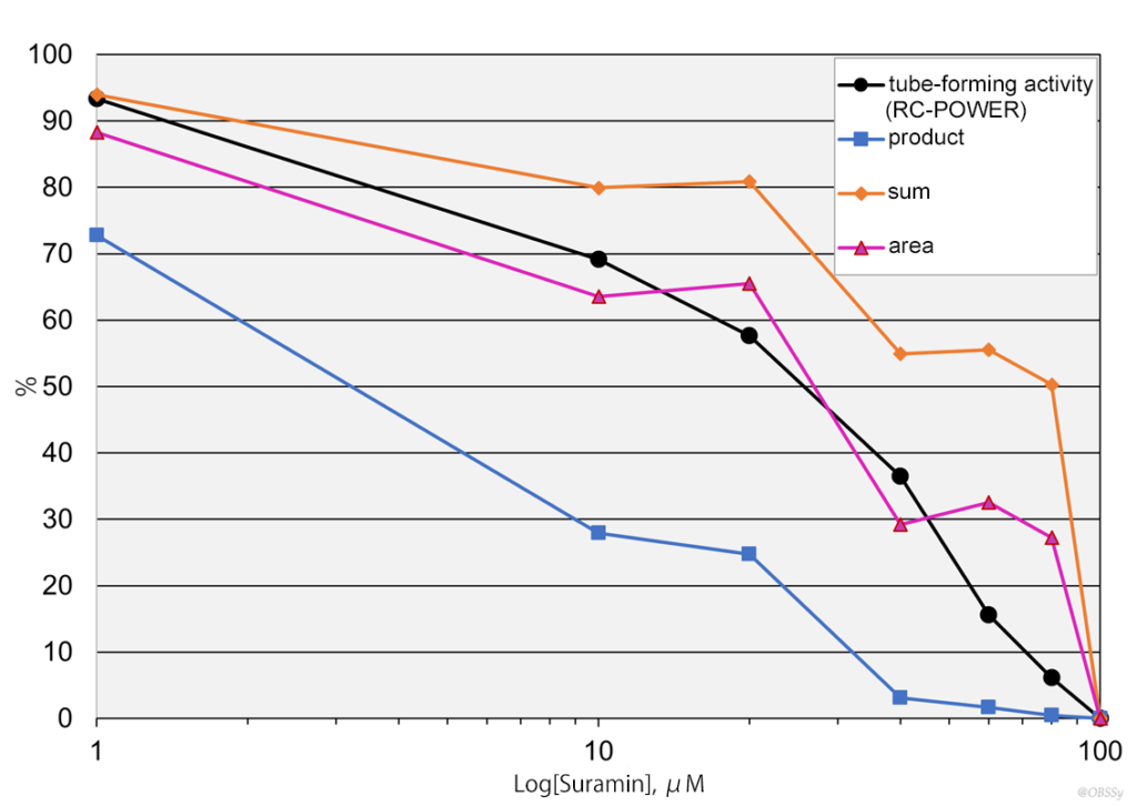
We obtained three integrated values from the scores from five perspectives of each dose by different calculations other than RC-POWER. They performed by their product, their sum, and the area of their radar chart. The values obtained are percentages of ones of the control. Figure 8 shows four inhibition processes with the tube-forming activity of RC-POWER and each integrated value.
Click to enlarge
Figure 8 Different inhibition processes depending on integration.
As with RC-POWER, only the product shows a gradual inhibition process that decreases as the doses increase. However, the values are smaller than those with the RC-POWER, and the change is difficult to discern in inhibition, especially at higher doses.
In the inhibition process with sum and area, the values increase once at high doses and then decrease. However, this increase is puzzling for the tube formation test by an anti-angiogenic agent used in clinical practice.
In the radar charts shown in Figure 6, some perspectives increase significantly at 60µM, while others become extremely small. Their sum and area of the radar chart must have increased. However, the shape of the radar chart becomes excessively unbalanced, resulting in a decrease in the RC-POWER.
Why do the identical five scores cause gradual inhibition or inhibition after increasing?
Integration according to how each event from multiple perspectives is perceived
A radar chart shows not only scores but also their balance and large or small using the shape and size of the formed polygon. Because of that, it is appropriate to show obtained scores when events researched with each perspective are assumed to have occurred together. It corresponds to the case when using the RC-POWER and the product.
In the case of the sum of the scores and the area of the polygon formed by the radar chart, the events are assumed not to have occurred together. The area is the sum of the areas of triangles formed by the adjacent score. Therefore, the sum and the area correspond to the same case and show the same inhibition process.
We had better be conscious of whether the events researched with multiple perspectives occurred together or not in the object. Because using an integration that is appropriate for this property of the events will lead us to an accurate understanding of the whole.
In particular, as in this example, when we calculate the integrated values after showing the scores from each perspective on a radar chart, the RC-POWER and the product are appropriate for the integration. Because their integration is under the same perceiving as we capture scores on radar charts when events occur together.
RC-POWER is an index of power that indicates whether the radar chart has well-balanced high scores. The integrated value by the RC-POWER is greater than the simple product of scores. Thus, changes in inhibition show clearly at high doses.
The RC-POWER is appropriate for integration to know the whole from research with multiple perspectives when the events with each perspective would occur together.
Summary
・ We usually research from multiple perspectives and show each obtained score on a radar chart to capture the whole visually.
・ The radar chart clearly shows not only their scores but also their balance and large or small using the shape and size of the formed polygon. The radar chart is appropriate to show obtained scores when events researched with each perspective are assumed to have occurred together.
・ When we calculate the integrated values after showing scores from each perspective on a radar chart, the integration is required under the same perception as we capture the scores on the radar charts.
・ RC-POWER calculated from the shape and size of the radar chart means whether the scores are high in a well-balanced manner or not. The RC-POWER is appropriate for integration to know the whole from research with multiple perspectives when the events with each perspective would occur together.
・ An example of the tube formation test shows that the half minimal inhibitory concentration was accurately estimated from the approximation of the numerical change of RC-POWER replaced from the sequence of the radar charts of the experimental results.
・ We had better be conscious of whether the events researched with multiple perspectives occurred together or not in the object. Because an integration that is appropriate for this property of the events will lead us to an accurate understanding of the whole.

